
TalTech Iseauto is developed by TalTech students of the School of Information Technologies and the School of Engineering and Silberauto AS. ABB has also contributed as one of the project’s partners.
While in the previous two posts we focused on the Mitsubishi i-Miev’s driving logic and the development of controlling algorithms for the Mitsubishi i-Miev test car, this time we will be introducing how the Iseauto bus was made in cooperation of TalTech’s School of Information Technologies and School of Engineering.
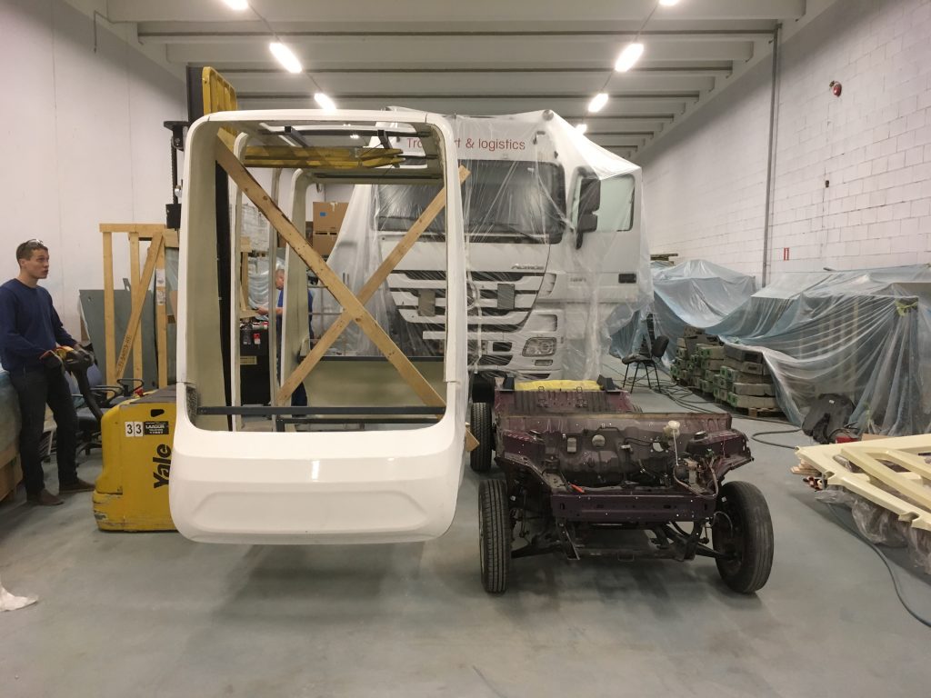
In the first post we talked about the need to first dismantle the existing Mitsubishi i-Mievi body to build a bus. Then you need to construct the body for the bus and finally install it. In all this, you need to take into account that the upcoming bus must be able to accommodate the hardware needed so that it can be continuously upgraded during its development. It is also important to hide all the hardware from the eyes of the passenger. In conclusion, designing a practical, user-friendly and expressive bus is a challenge for engineers and designers alike.
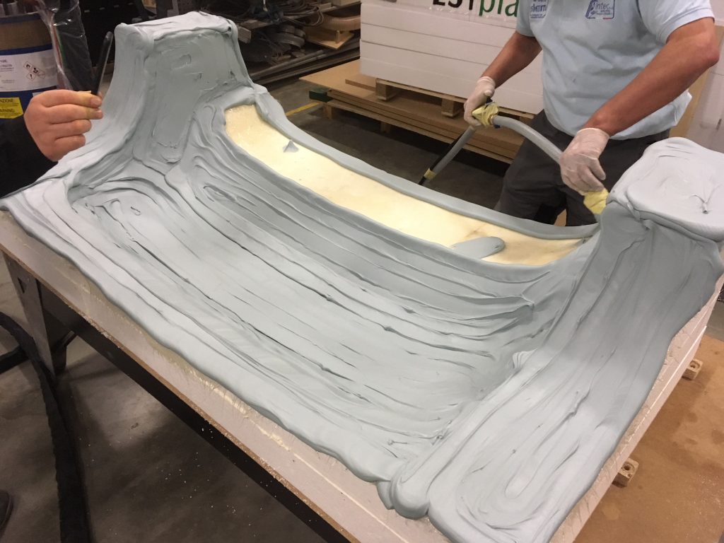
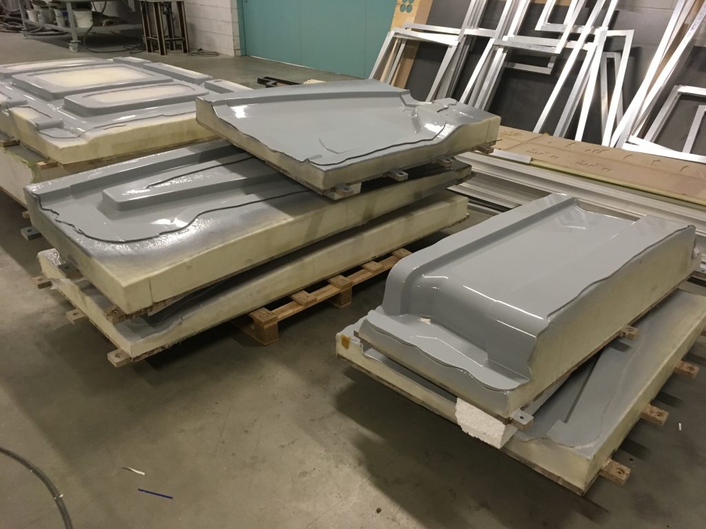
Silberauto AS, who, as we already know, is the largest partner in the project given to TalTech, was in charge for the design and production of the car body. The following pictures show how the molds were made, how they look like and how the final body of the car was mounted on the undercarriage.
Two big metal boxes were placed in the front of the car to accommodate the necessary hardware. One box is a personal computer, and the other for controllers and other equipment needed.
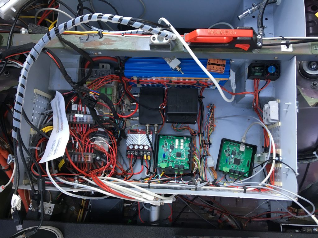
The control of the bus is to a large extent similar to the test car, but still has a few significant differences. The most notable of these is the control of the brakes. In total there are three different ways to stop the bus.
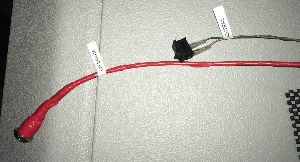
If we used an electronic handbrake as an emergency brake on our test car, then on the bus the electronic handbrake doesn’t have enough stopping force and this solution is not durable enough. So, we decided to use the brakes of the Mitsubishi i-Miev for braking. For this, however, we needed to add an electronic brake pump to the car. With the brake pump, we can pump pressure onto the brakes, but this is not enough. In the first post, we mentioned that in addition to the brakes that the management of solenoids is also important. We made sure that we only need to manage two different solenoids so we can use the brakes. The logic for the solenoids is easy to understand – in order to create pressure the solenoids must be activated. If they are deactivated, the brakes are released. Because we needed to know how much force was applied to the brakes, we added a pressure sensor to the braking system. With the help of an analogue-to-digital converter, the pressure sensor allows us to see the force applied to the brakes.
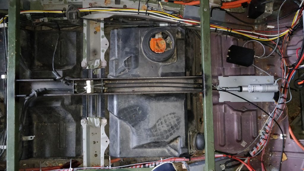
In addition to the usual brakes, the bus has a different handbraking system. Namely, there are two handbrakes on the bus – one manual and one electronic. The electronic handbrake is controlled by a linear actuator (read more here) mounted on the bottom of the car. The manual hand brake lever is placed between the boxes for the hardware of the car. Both handbrakes are connected to the i-Miev’s original handbraking cable, by pulling the cable sufficiently the brakes activate. The steering wheel, gearbox, and acceleration management behave in exactly the same way as on the test car.
In essence, three different brakes, that we have on the bus were described. Why do we need so many of them? One of the most important aspects of Iseauto is safety and the more ways we can stop a car, the better. As already described, we can not manually turn the steering wheel or press down on the brakes. Therefore, getting the car to stop in the event of danger has to be done with electronic solutions in most cases. The only exception to this is the manual handbrake.
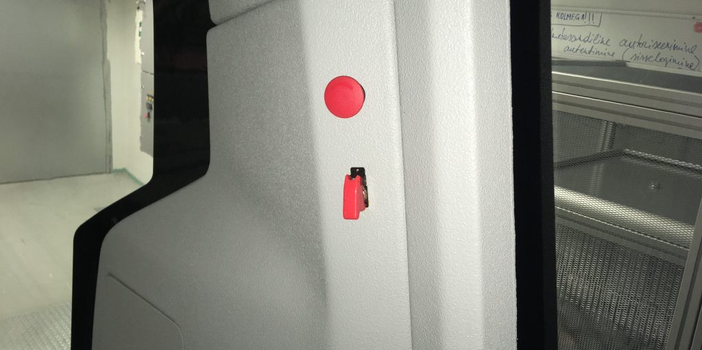
Besides the mechanical brake, there are three options on the bus for the application of brakes.
The first and so far most used emergency brake button is connected directly to the drive controller and when it is pressed, the drive controller applies the brakes with maximum force. The advantages of this button are that the braking force is high and the time needed to apply the brakes is short. Also, when the button is released, you can resume the ride immediately. The disadvantage, however, is that if the drive controller does not work for some reason, the bus cannot be stopped through this button.
The next option to stop the car is with the help of a large red emergency button, which we have placed on the front of the car. When this button is pressed, the engine is turned off in the vehicle and the electronic hand brake operates. The advantage is that, because the car’s engine is turned off, the car will continue to run in a free motion, so to say the car doesn’t receive additional power from the engine. However, the activation of the electronic handbrake lasts for several seconds, and therefore the braking distance is longer. However, the braking distance can be lessened, by also using the manual hand brake.
As the most recent solution, we still have a switch in the car, which disconnects the engine from the battery. For this solution, we can rest assured that the car switches to “idle” and the engine will not be used to move forward. However, the disadvantage is that no brake is directly applied and after pressing this button and it is necessary to delete the error code from the control unit afterwards. There has been no reason to use this button in testing yet.
Unlike the test car, there are some improvements to the bus. The first of these are LED strips that are applied to the front and rear of the bus. Each LED is accompanied by a controller that changes the colors of the lights according to the command given to it by the CAN (controller area network).
Secondly, it necessary to control the bus door, for that we also have an controller. This controller also reacts to commands given by the CAN.
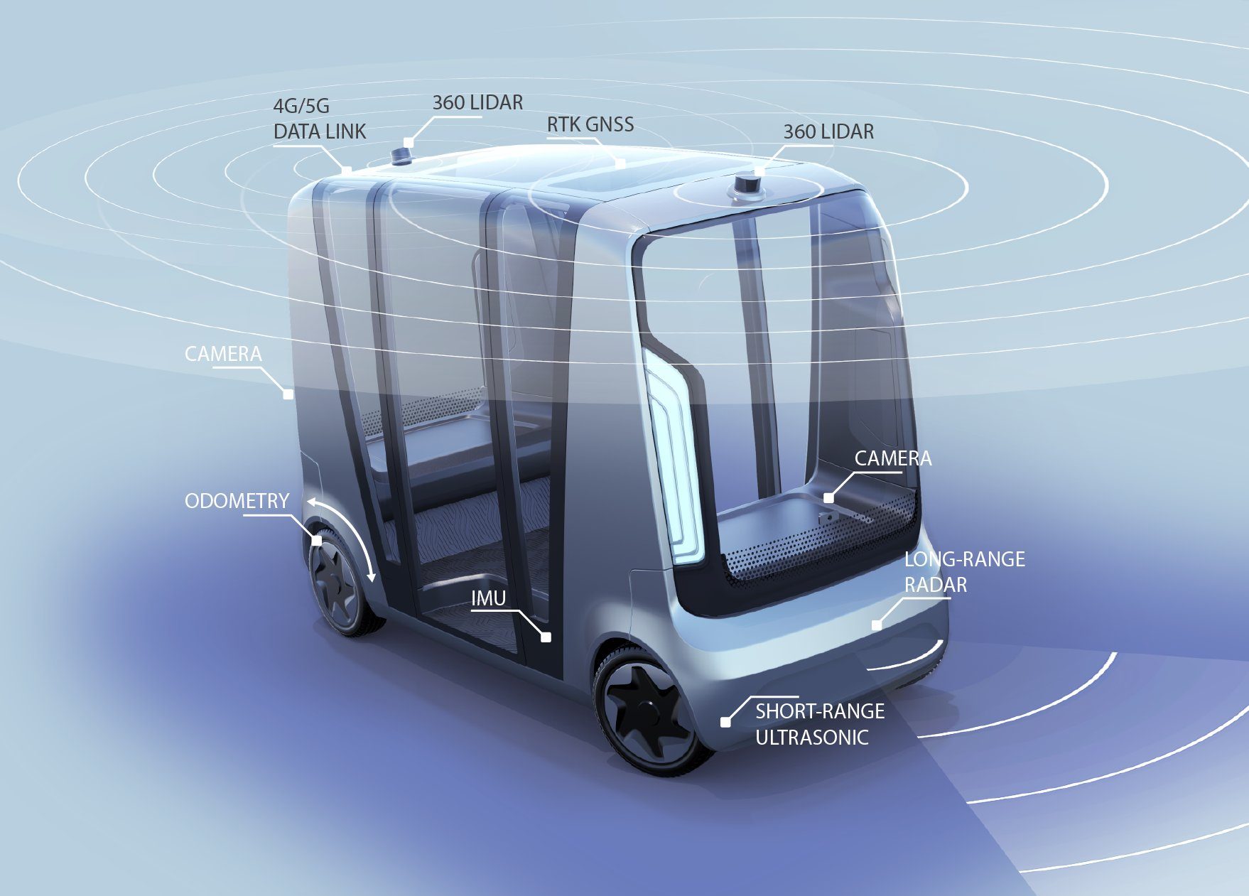
Thirdly, 8 ultrasonic sensors have been added to the bus, unlike the test car. Four of these are located on the front and four of these are located on the back. To obtain and transmit information from the sensor, there are controllers one for the front and one for the back, that collect information from the sensors and output the distance from any object to the CAN in decimeters.
In all, the important components of the bus have been talked about. Next time, let’s look at what the bus looks like, how and what sensors were placed on the bus and what Iseauto is capable of and what is its future.
The Ministry of Education and Research and the Estonian Research Council are supporting the completion of the blog.