
TalTech Iseauto is developed by TalTech students of the School of Information Technologies and the School of Engineering and Silberauto AS. ABB has also contributed as one of the project’s partners.
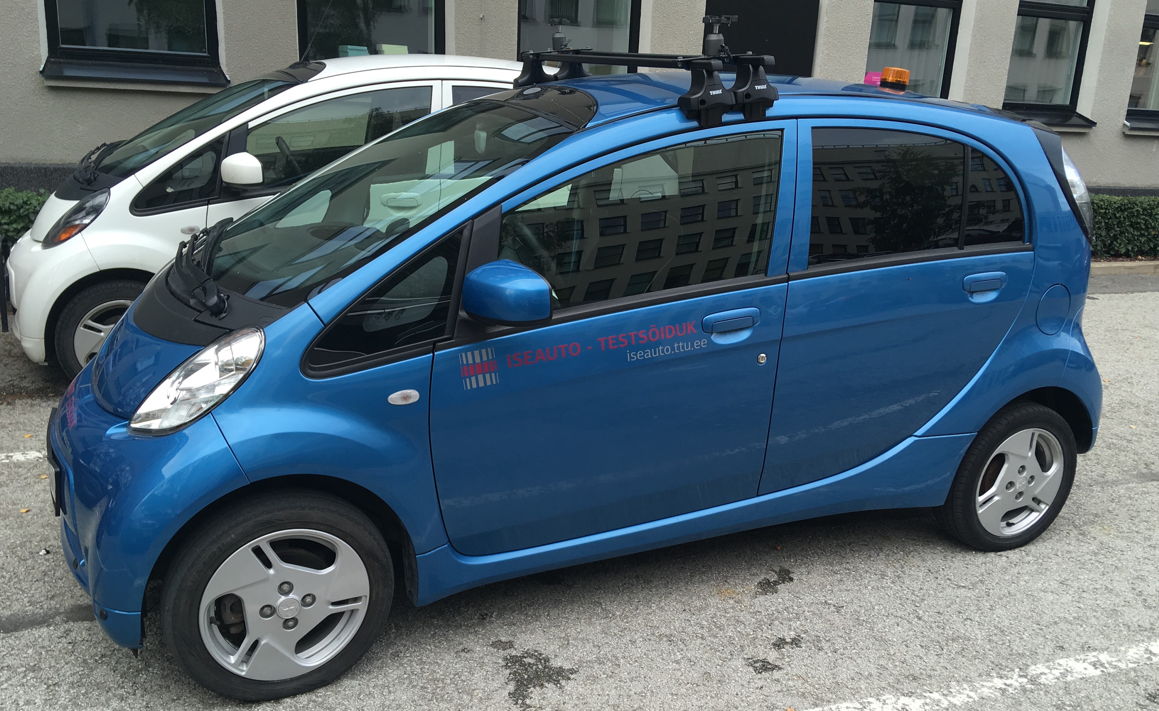
Last time, we briefly introduced the TalTech Iseauto project and the underlying Mitsubishi i-Mievit with its control logic. This time, we will introduce the self-made controllers installed in Iseauto, their needs and why one or the other controller is necessary for driving the Iseauto. The first tests are done with the testcar in the picture below, which has become our platform to help us test all our hardware and software. Since many experiments were needed during the first development phase, we have modified test car has to be used for both self-driving and manual mode, if necessary.
The use of microcontrollers in my car is inevitable because they help to generate the same signals for driving a car that is caused by a person when he rotates the car, presses gas or brake pedal or the changes gear. A microcontroller can have up to several hundreds of input/output pins, all of which can be programmed as needed. In the Iseauto project, we use the controllers produced by STMicroelectronics. The main reasons for using them are a wide range of different controllers, big community, a convenient development interface and, of course, our past experience with their use.
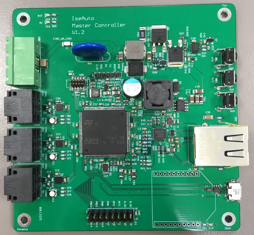
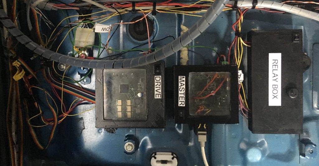
TalTech Iseauto has about ten different controllers already. Some of them are made by the car manufacturer, and we still use them, and some of them have been replaced by our own developed controllers. In this post, we focus on two main controllers – we call them Drive and Master. The drive controller’s task is to control equipment used for driving the car. The main task of the master controller is to communicate information between different controllers and the personal computer. The following figure shows Master Controller Version 1.2. On the left side you can see the power connectors and the 3 CAN connector and on the right side is the ethernet jack.
Master controller
The main task of the master controller, the transmission of information to the correct controller, depends on what kind of data a controller needs. Some of the data can be transmitted at a certain interval, the time-critical data needed to make quick decisions is transmitted immediately upon arrival.
The master must be able to communicate in both directions with other controllers, i-Miev’s electronic control unit (ECU) and with a personal computer (PC). The ECU communicates with other devices via the CAN bus, and the fastest way for PC to communicate with the controller via an ethernet. We decided that it would be most sensible to communicate with controllers via the CAN bus. Therefore, the first requiremet for Master controller is that it has to support the ethernet interface, and it also has to have at least three CAN interfaces to communicate with the controllers and the ECU. We found that the appropriate controller is STM32F767.
The CAN bus used for transmitting information is capable of transmitting messages in essence with only one particular protocol. These messages have one 11-bit or 29-bit identifier and up to 8 bytes of message. We use 11-bit identifiers in the project. With ethernet it is possible to use different protocols, but the UDP protocol is suitable for us, which does not require an on-the-spot confirmation. On the one hand, there is no need to send an acknowledgment of receipt of a message because the messages are sent 100 times per second. If one message is not received, the delay in the car is about 10ms, which is not critical for a vehicle moving up to 20 km/h. On the other hand, each message comes with its own counter, which allows us to automatically detect the differences in the number of sent and received messages, and to identify possible problems in hardware and software.
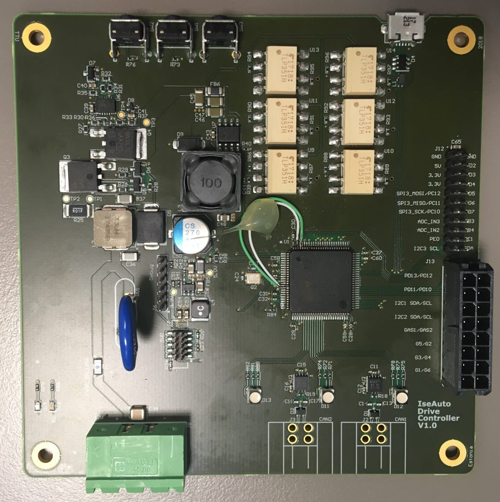
Another and considerably more complicated controller is the Drive controller. As mentioned above, his task is to drive the car – in other words, drive the car’s accelerator, brakes, steering wheel and gear lever. When we got to the Mitsubishi i-Miev’s control logic last time, this time we look at how the controller can mimic this control logic.
Let’s start the accelerator. As mentioned in the previous post, we need to generate two analogue voltage signals, where the MAIN signal must be twice as high as the SUB signal. Such analogue voltage signals are generated by a digital-to-analogue converter (DAC). The drive controller uses the STM32F407 microcontroller which has two built-in DACs, which we use.
To rotate a steering wheel, we need to drive a power electric motor. The direction of current flow determines at which direction and the strength of current how fast the wheels are rotated. To do this, we use the H-bridge as an electronic switch to control the electric motor in both directions. We have installed an H-bridge, which allows us to control the current through pulse width modulation. Who wants to read more about the operation of the H bridge, then one place is, for example, here.
Transmission control is extremely simple, it is necessary to direct a high voltage level to the correct ECU input. If the microcontroller’s normal operating voltage is either 3.3V or 5V, then the gearbox’s high voltage level signal must be 12V. It makes things a bit more complicated. In order to switch the 12V with 3.3V, we use optocouplers on Iseautol, which will electrically disconnect the controllers from the control signal of the car. This helps to protect our controllers if the car system should cause interference or some components to spoil and cause Drive controller to burn down.
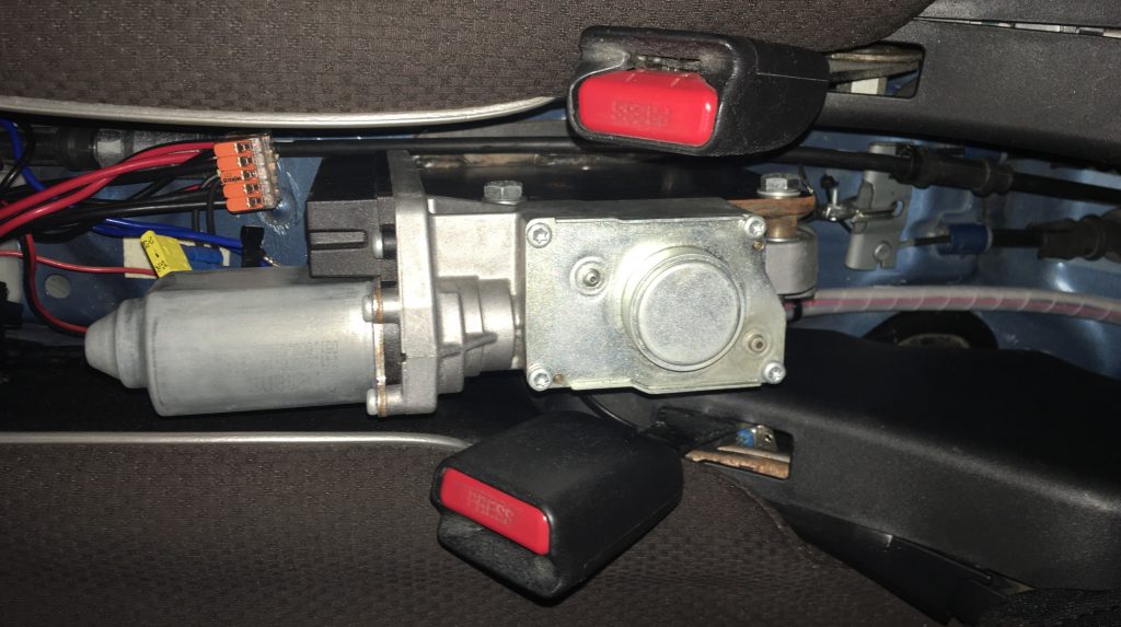
In the development of the braking system in our car test drive, we had to take into account that we would have left the car braks in the trench so that we could use them if necessary. Therefore, we decided to use the BMW electronic handbrake as a brake, which we placed in the car instead of a mechanical handbrake. Since the car’s electrical handbrake is usually driven through the CAN interface, but we did not have the specification for the handbrake, we removed the handbrake control electronics and control the electric powertrain on the handbrake directly. Since this handbrake engine must also be driven in both directions (on and off), the H-bridge has to be used. Since we did not use the built-in handbrake limit switches (to understand how much the handbrake was on or off), we added the flow control sensors for the motor control circuit. If the power consumption of the handbrake engine exceeded the reference value, then we stopped pulling or releasing the handbrake. We also need to know in which handbrake is. To do this, we use an encoder built into the handbrake that gives the impeller every half-turn of the handbrake engine. It allows you to read the engine speed, or find out the current position of the engine.
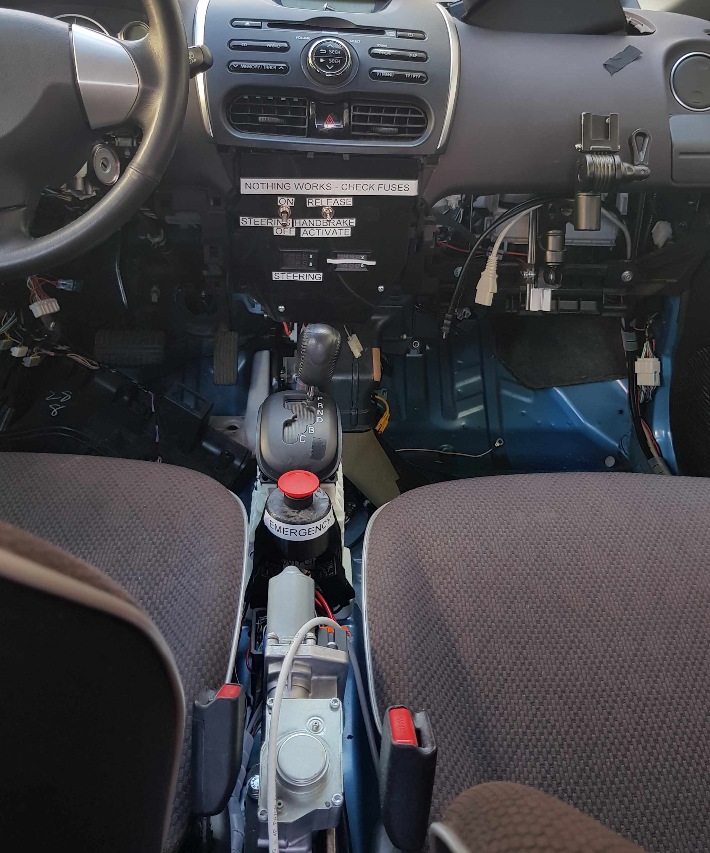
Now we had everything necessary for testing – we were able to rotate the steering wheel, keep it in proper speed and turn on the desired gear. At last we added a relay box to the car, which allows us to turn the self-driving mode into manual driving mode for development purposes.
The Ministry of Education and Research and the Estonian Research Council are supporting the completion of the blog.